QPSK stands for Quadrature Phase Shift Keying.
Definition: It is one of the widely used Digital Modulation techniques and is a form of Phase Shift Keying in which two bits are modulated at once, selecting one of four possible carrier phase shifts (0, 90, 180, or 270 degrees).
QPSK allows the signal to carry twice as much information as ordinary PSK using the same bandwidth. Thus, the amount of radio frequency spectrum required to transmit QPSK reliably is half that required for PSK signals, which in turn makes room for more users on the channel.
Figure below shows a QPSK modulated waveform:


QPSK generation involves following steps:
Step1: At the input of the modulator, the digital data’s even bits (i.e., bits 0,2,4 and so on) are stripped from the data stream by a “bit-splitter” and are multiplied with a carrier to generate a BPSK signal (called PSKI).
Step2: At the same time, the data’s odd bits (i.e., bits 1,3,5 and so on) are stripped from the data stream and are multiplied with the same carrier to generate a second BPSK signal (called PSKQ).
NOTE: The PSKQ signal’s carrier is phase shifted by 90 degrees before being modulated.
Step3: The two BPSK signals are then simply added together for transmission and, as they have the same carrier frequency, they occupy the same portion of the radio frequency spectrum.
Advantage of using 90 degrees phase shifted carriers: The required 90 degrees of phase separation between the carriers allows the sidebands to be separated by the receiver using phase discrimination.
The constellation diagram of QPSK is as shown below:


Here, we have two product detectors to simultaneously demodulate the two BPSK signals.
Advantage of simultaneous demodulation: It helps in recovering the pairs of bits in the original data simultaneously.
Step1: The incoming signal is simultaneously fed to 2 product detectors which basically act as comparators.
One input to the detector is the incoming QPSK signal and another one is the local oscillator.
Note: Remember, signal sent from the modulator is addition of two signal components one is in-phase (with the carrier) and other one is quadrature (with the carrier that is 90 degrees phase shifted)
Q. How does the detector/comparator works and which signal is carried forward and which is rejected?
Ans. The detector takes in the incoming QPSK signal and the local oscillator.
That part of the signal carried forward for which the phase of the carrier matches with the phase of the local oscillator and the part of the signal that is out of phase gets rejected.
For one detector, the local oscillator is fed directly and for the other detector it is shifted by 90 degrees.
Step2: Next, the outputs of the detectors are treated to remove the carrier and the original even bits are obtained from the In-phase component and the odd bits are obtained from the Quadrature component.
Step3: The bits are combined using the parallel to serial converter and the original data is obtained.
Source: IIT Sakshat Virtual Labs
http://www.rfwireless-world.com/Terminology/QPSK.html
Q. What is Modulation?
Q. What is the use of a carrier in Modulation?
Q. What is Digital Modulation?
Q. What do you mean by baseband signal ?
Q. What do you mean by bandwidth of a signal?
Q. What do you mean by RF and what is it used for?
Q. What are sidebands?
Q. What is a constellation and what does it represents, what is it used for?
Q. What is BER?
Q. What is Phase Shift Keying?
Q. What is BPSK?
Q. What is the raised cosine and its use and advantages of using it?
Q. How do signal analyzer find I an Q signals?
Definition: It is one of the widely used Digital Modulation techniques and is a form of Phase Shift Keying in which two bits are modulated at once, selecting one of four possible carrier phase shifts (0, 90, 180, or 270 degrees).
QPSK allows the signal to carry twice as much information as ordinary PSK using the same bandwidth. Thus, the amount of radio frequency spectrum required to transmit QPSK reliably is half that required for PSK signals, which in turn makes room for more users on the channel.
Figure below shows a QPSK modulated waveform:
QPSK modulator:
Following is the block diagram of a QPSK signal generation:QPSK generation involves following steps:
Step1: At the input of the modulator, the digital data’s even bits (i.e., bits 0,2,4 and so on) are stripped from the data stream by a “bit-splitter” and are multiplied with a carrier to generate a BPSK signal (called PSKI).
Step2: At the same time, the data’s odd bits (i.e., bits 1,3,5 and so on) are stripped from the data stream and are multiplied with the same carrier to generate a second BPSK signal (called PSKQ).
NOTE: The PSKQ signal’s carrier is phase shifted by 90 degrees before being modulated.
Step3: The two BPSK signals are then simply added together for transmission and, as they have the same carrier frequency, they occupy the same portion of the radio frequency spectrum.
Advantage of using 90 degrees phase shifted carriers: The required 90 degrees of phase separation between the carriers allows the sidebands to be separated by the receiver using phase discrimination.
The constellation diagram of QPSK is as shown below:
Each adjacent symbol only differs by one bit. QPSK is also known as quaternary or quadriphase PSK or 4-PSK because of the four points on the constellation diagram, which are equispaced around a circle and hence providing four different phases.
When we write the symbols in the constellation diagram in terms of sine and cosine waves used to transmit them, it yields the four phases π/4, 3π/4, 5π/4 and 7π/4 as needed.
This results in a two dimensional signal space with unit basis functions.
1. The first basis function is used as the in-phase component of the signal and
2. the second as the quadrature component of the signal.
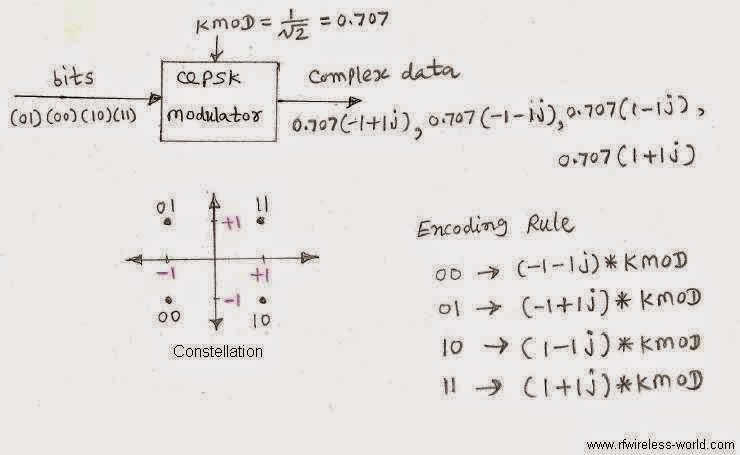
Thus, QPSK converts two binary bits represented simultaneously at the input to the complex signal S(t) or d as mentioned. This complex signal selects one of the four phases based on two binary digits. Each state of the complex signal or waveform is called as symbol.
The QPSK signal representing different bits is as shown here:

The QPSK signal representing different bits is as shown here:
Also, in the compact form, the QPSK signal can be shown as below.
Advantages of using QPSK:
1. QPSK can encode two bits per symbol shown in the diagram to minimize the BER- twice the rate of BPSK.
2. QPSK may be used either to double the data rate compared to a BPSK system while maintaining the bandwidth of the signal or to maintain the data rate of BPSK but half the bandwidth needed.
QPSK demodulator:
Advantage of simultaneous demodulation: It helps in recovering the pairs of bits in the original data simultaneously.
Step1: The incoming signal is simultaneously fed to 2 product detectors which basically act as comparators.
One input to the detector is the incoming QPSK signal and another one is the local oscillator.
Note: Remember, signal sent from the modulator is addition of two signal components one is in-phase (with the carrier) and other one is quadrature (with the carrier that is 90 degrees phase shifted)
Q. How does the detector/comparator works and which signal is carried forward and which is rejected?
Ans. The detector takes in the incoming QPSK signal and the local oscillator.
That part of the signal carried forward for which the phase of the carrier matches with the phase of the local oscillator and the part of the signal that is out of phase gets rejected.
For one detector, the local oscillator is fed directly and for the other detector it is shifted by 90 degrees.
Step2: Next, the outputs of the detectors are treated to remove the carrier and the original even bits are obtained from the In-phase component and the odd bits are obtained from the Quadrature component.
Step3: The bits are combined using the parallel to serial converter and the original data is obtained.
Source: IIT Sakshat Virtual Labs
http://www.rfwireless-world.com/Terminology/QPSK.html
Q. What is Modulation?
Q. What is the use of a carrier in Modulation?
Q. What is Digital Modulation?
Q. What do you mean by baseband signal ?
Q. What do you mean by bandwidth of a signal?
Q. What do you mean by RF and what is it used for?
Q. What are sidebands?
Q. What is a constellation and what does it represents, what is it used for?
Q. What is BER?
Q. What is Phase Shift Keying?
Q. What is BPSK?
Q. What is the raised cosine and its use and advantages of using it?
Q. How do signal analyzer find I an Q signals?
No comments:
Post a Comment